DoITPoMS Teaching and Learning Packages
Optical Microscopy and Specimen Preparation
Polarised Light Microscopy
|
Under normal
circumstances, light vibrates equally easily in all
directions perpendicular to the direction of
propagation. Light passing through a polariser is
modified so that the light transmitted vibrates in
only one direction - this is polarised light. This
direction is parallel to the planes of the
polarising material.
If light is polarised in one direction and then passed through a polariser at a different angle to the original polariser, only the component of the polarised light which is in the same direction as the new polariser will be transmitted. If the second polarisation direction is at 90° to the original polarisation direction, the arrangement is known as "crossed polars" and the second polariser is referred to as the analyser. In this arrangement extinction usually occurs, i.e. no light is transmitted, because there is no component of the polarised light which can pass through the second polariser. In an isotropic material, for example a cubic crystal, or an amorphous material, light vibrates equally easily in all directions. These materials do not affect polarised light. If an isotropic material is examined between crossed polars, extinction occurs, and the image appears dark. 
When a light ray enters an optically anisotropic crystal (other than along an optic axis ), it is resolved into two rays - an ordinary ray (or O-ray) and an extraordinary ray (or E-ray). These rays vibrate in fixed planes at right angles to each other. When the rays arrive at the analyser, those components of their vibration directions which are parallel to the polarisation of the analyser are transmitted, while those components which are perpendicular are absorbed. The rays travel with different velocities through the crystal. The ordinary ray travels with the same velocity in all directions and the extraordinary ray travels with a direction-dependent velocity. When the O-rays and E-rays emerge from the crystal the phase of one set of rays is retarded with respect to the other. This retardation depends on the difference in velocities of the two rays and the thickness of the specimen. Such a crystal is said to exhibit birefringence . 
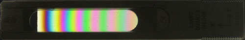
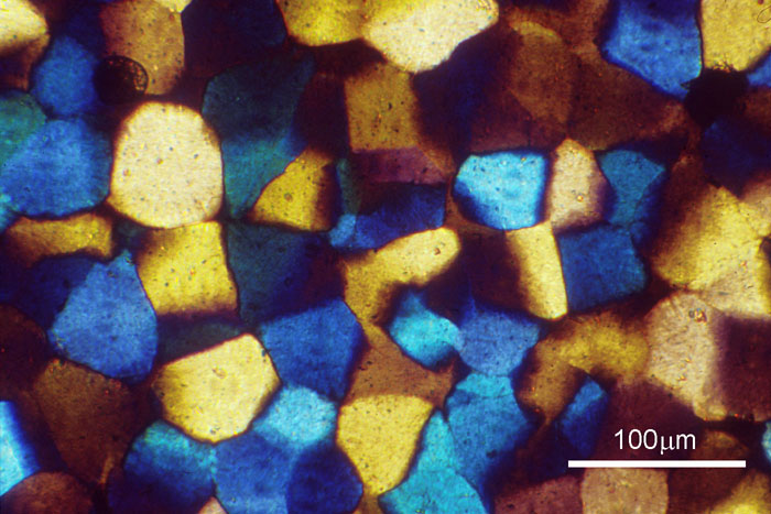
The two transmitted rays interfere, and the effect produced depends on the phase difference between the O-rays and E-rays and their amplitudes at the analyser. Extinction occurs when the optical path difference between the O-ray and the E-ray is a whole wavelength. When white light is used, anisotropic crystals may appear coloured when viewed between crossed polars, due to interference effects between rays emerging from the analyser. Certain wavelengths, and therefore certain colours, will be extinguished due to destructive interference. The colours seen depend on the birefringence of the crystal, its thickness, and the orientation of the section relative to the optic axis. Colour variations are observed within each grain as the stage is rotated. A quartz wedge viewed between crossed polars shows how the colour of the light changes as the retardation increases. In the photo below, the wedge increases in thickness from left to right. As the thickness increases, the retardation also increases. The relation between retardation, birefringence and thickness can be seen on a Michel-Levy chart.
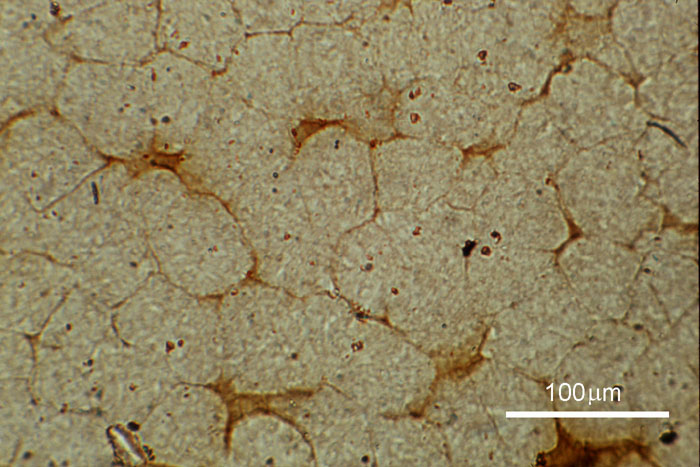
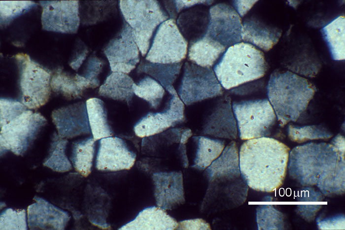
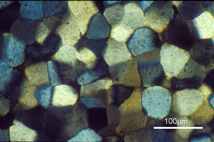
Quartz wedge viewed between crossed polars A polarised light microscope has a polariser and analyser fitted at 90º to each other in an illuminating system. The arrangement also allows for the insertion of plates at 45º to the planes of polarisation. These can be used to enhance the contrast in a specimen. For further effects, it is also often possible to rotate one of the polarisers if crossed polars are not to be used. When observing a specimen, differences in birefringence allow phases and grains to be identified. For example, different grain orientations may exhibit differences in birefringence and this will cause them to appear a different colour. Enhanced colouration of the image observed under crossed polars can be obtained by insertion of a full wave sensitive tint plate (also known as a red tint plate). The series of photos below shows the difference in the appearance of some glass ceramic specimens as different plates are inserted.
|
||||||||
|
© University of Cambridge DoITPoMS, Department of Materials Science and Metallurgy, University of Cambridge |